Ebeam Evaporator Standard Operating Procedure – Revision 02
Author: Mario Beaudoin, September 2015. Rev. 02, April 2021. Rev. 03, January 2023.
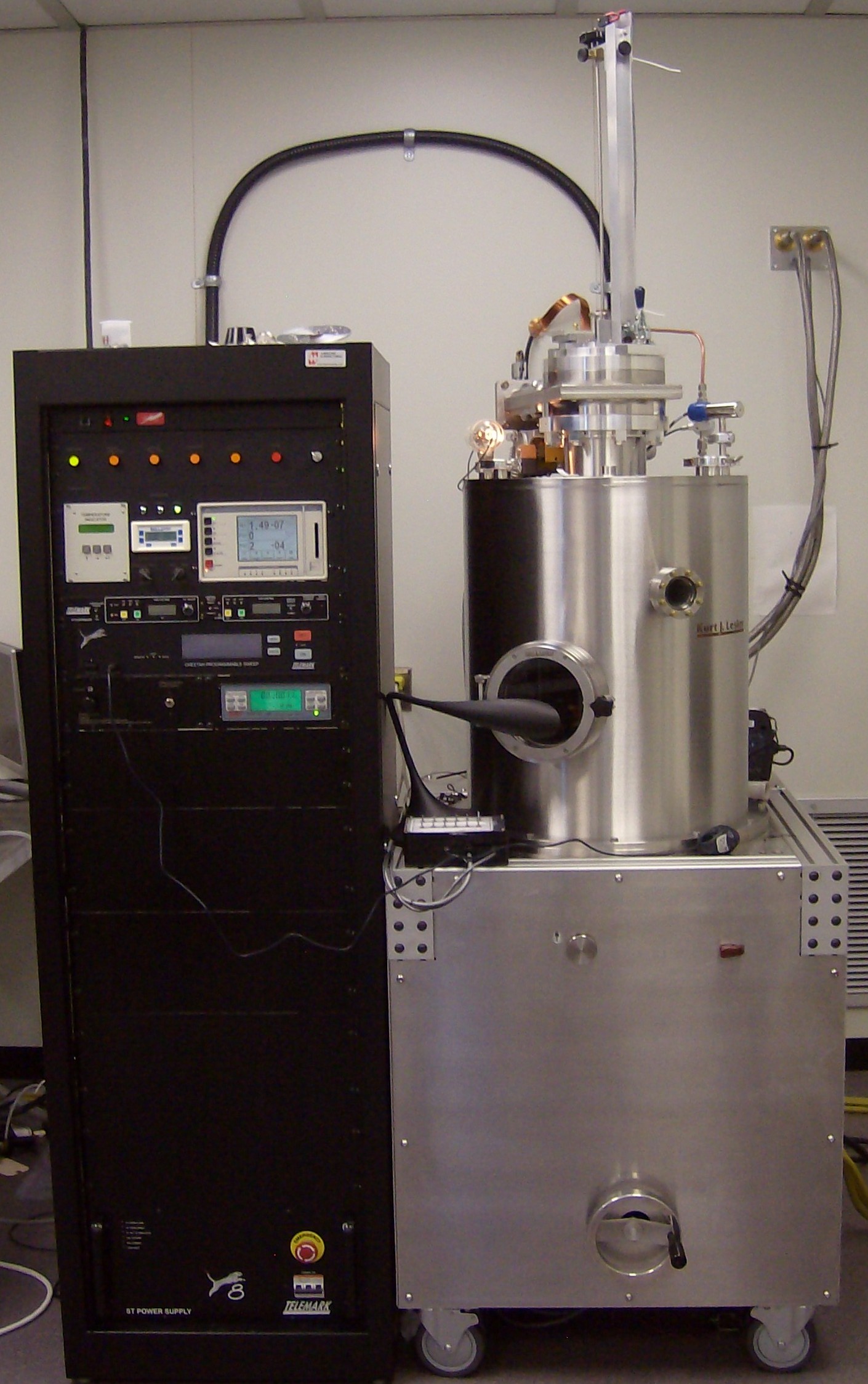
Figure 1: DeeDirectors2015 8 source electron beam evaporator.
Purpose: To describe how to use the evaporator for Physical Vapor Deposition (PVD) by Electron Beam heating. This is a custom built system designed by the cleanroom co-directors, Profs Joshua Folk and Lukas Chrostowski, and engineered by Doug Wong and Jim Mackenzie. It features a load-lock loading mechanism and 8 evaporation sources. We are naming it the DeeDirectors Evaporator. This system is NOT automated and is to be used in FULLY MANUAL MODE only (at least for now). This SOP is meant to be used by properly trained operators only.Introduction
The DeeDirectors system is a vacuum process system for Physical Vapor Deposition (PVD) of metals and non-metals, consisting of an electronics control rack, E-beam power supply, Cryo pump and compressor and a dry mechanical vacuum pump. The system is oil free.
The electronics rack houses the Ion and thermocouple vacuum gauge controllers, the thickness monitor, Cryo pump temperature monitor and the E-beam power supply, including its controls for beam power, intensity and sweep. While the system is interlocked for safety purposes, since it is operated in full manual mode, it is possible to cause downtime and minor damage to the system if not properly operated.
Operation
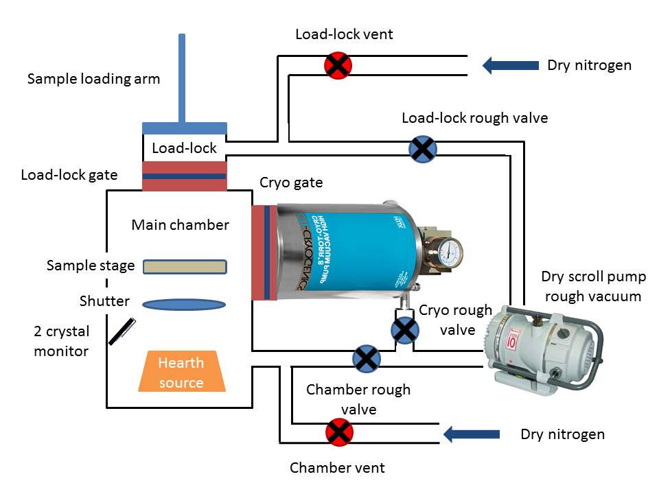
Figure 2: Schematic of evaporator.
Figure 2 shows a schematic diagram of the evaporator. The main chamber is normally kept under high vacuum while samples can be loaded through the load-lock chamber (loading is explained below). The chambers are isolated from each other and from the pumps by sets of pressure activated valves. During normal idle operation, both the load-lock rough valve and the cryo gate valve remain open; this ensures high vacuum in the main chamber and a few mTorr vacuum in the load-lock chamber. All other valves are closed.
The main chamber is isolated from the load-lock through the load-lock gate valve. This valve should only be operated when the load-lock pressure is less than 50 mTorr as read on the Lesker gauge (Figure 3). In normal operation, only the load-lock gets vented to atmosphere to allow loading/unloading of samples. Venting is done by opening the load-lock vent valve to let in dry nitrogen.
Controls

Figure 3: Electronics rack with vacuum, temperature and electron beam controls. Blowups show Ion Gauge controller/readout, Crystal monitor controls/readout and load-lock vacuum readout.
Figure 3 shows a picture of the electronics rack for the system along with larger pictures focussing on the ion gauge controller, the crystal monitor controller and the Lesker load-lock vacuum monitor. The rack also houses the cryopump temperature monitor and the electron beam (ebeam) controller. The ebeam controls are for the high voltage (HV), the beam current and the beam sweep mode.
The main chamber should always be found in the 10-7 Torr range after an overnight of idle operation and the load-lock should be in the few mTorr range. The load-lock should always remain isolated from the main chamber if its pressure is more than 50 mTorr.
Valves and Shutters Control Box
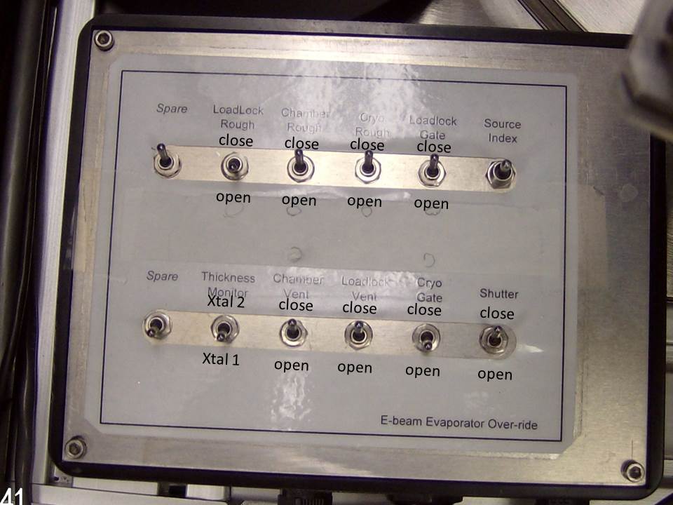
Figure 4: Valves and shutters control box.
The evaporator valves, as well as the main and quartz crystals shutters, are operated from the control box shown on figure 4. One needs to have a thorough understanding of the different chamber arrangements and the pumping scheme in order to safely operate the system. Wrong operation can cause damage and downtime such as:
- burning the ion gauge filament
- cracking a hot crucible/oxidizing pure metal
- saturating the cryopump, thus forcing a regeneration
- all of the above.
It is thus important to understand how the chambers are designed together as shown on figure 2.
Sample loading
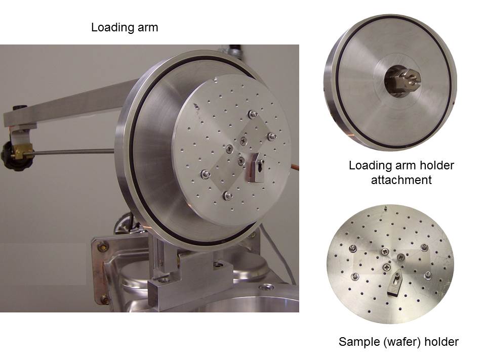
Figure 5: Loading arm mechanism.
Sample loading is potentially the most difficult part of using the evaporator. Figure 5 shows the loading arm mechanism with the load-lock open. The load-lock is opened, using the Valves and Shutters control box, by following these steps:
- Make sure the Loadlock Gate is closed
- Close the Loadlock Rough valve if it is open
- Vent the Loadlock by opening the Loadlock Vent valve
- When the Loadlock has reached atmosphere (reading over 400 on pressure monitor),
- Unclamp the Loadlock door and open it
- Close the Loadlock Vent valve
- Install (or remove) sample holder from loading arm
- Close the Loadlock door
- Open Loadlock Rough valve to bring the Loadlock under vacuum.
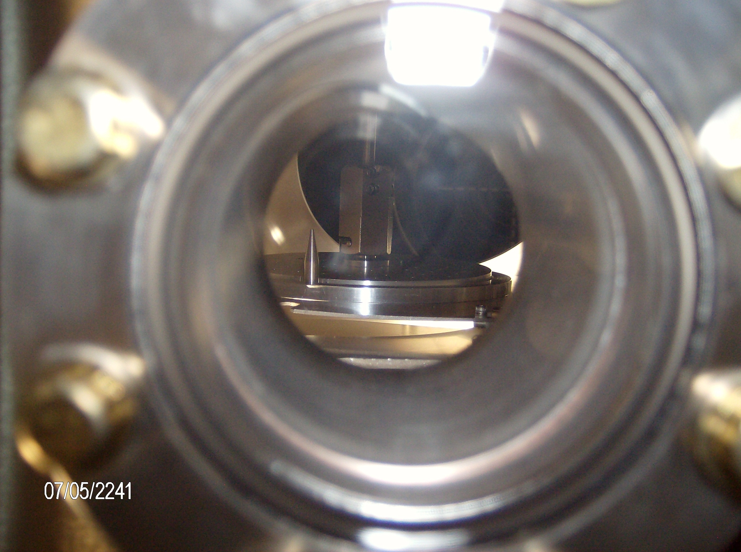
Figure 6: View through the top viewport of the sample being loaded on the sample stage inside the main chamber.
The sample is held on the sample holder with screws and washers (or clamps). The sample holder is then fixed to the loading arm attachment using a twist lock arrangement as shown on figure 5. When the Loadlock has reached a vacuum of 20 mTorr or less, the sample may be loaded into the main chamber:
- Make sure the Loadlock pressure is below 20 mTorr.
- Close the Loadlock Rough valve
- Open the Loadlock Gate
- Release the loading rod by unscrewing the top knob
- Turn on the LED lamp to provide illumination inside the main chamber
- Lower the loading arm into the chamber while looking at the sample stage through the top viewport (refer to figure 6)
- Note from figure 6 that the sample holder has a notch on its edge that needs to be aligned with the needle on the sample stage
- Make sure that the sample holder is fully inserted into the sample stage
- Release the arm from the sample holder by pushing down on the rod while twisting counter clockwise
- Fully retract the loading arm and secure it using the top knob
- Close the Loadlock Gate valve.
- Open the Loadlock Rough valve.
Programming the crystal monitor
The evaporation rate is measured using quartz crystals with a 6 MHz resonance frequency (Actually 5.950 MHz for a new crystal without deposition on it). As material is deposited on the crystal, its frequency shifts depending on the mass and elasticity of deposited material. Knowing the density of the material and its elastic properties allows calculation of its thickness. The elastic properties of the material are represented by the Z-ratio (sometimes referred to as Z-factor). The density and Z-ratio for common evaporants are summarized in the following density and Z-ratio table. Additionally, a material independant geometric factor, referred to as the tooling factor, accounts for the different position of the quartz crystals and the actual sample on which deposition occurs.
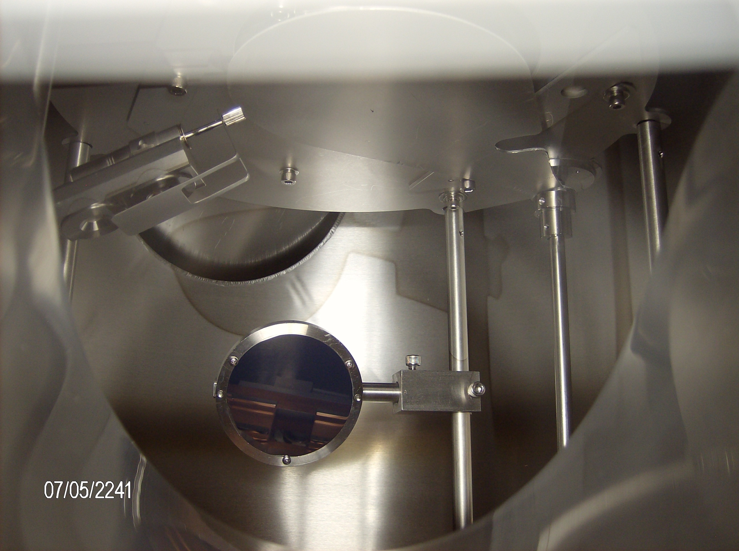
Figure 7: inside view of the main chamber. The 2 quartz crystal heads are visible on the left, a mirror in the center of the image shows the source. The closed main shutter is visible at the top of the image.
On the DeeDirectors evaporator, there are 2 crystals inside the chamber with a shutter to chose which crystal is used for any particular monitoring as show on Figure 7 (NB: only crystal 1 is available until further notice as crystal 2 is broken). The crystal choice is controlled by the Thickness Monitor switch on the control box: Xtal 1 is the bottom crystal and Xtal 2 is the top crystal.
The quartz crystals are controlled with the Sycon STM-100 crystal monitor shown in Figure 3. The crystal being monitored is chosen by the switch on the electronics rack located to the left of the STM-100 (also visible on Figure 3). The monitor keyboard is divided into two separate groups. The keys to the left are control keys and the keys to the right are programming keys.
Only the ZERO and LIFE keys are active on the left side of the keyboard as the shutter is actuated from the Thickness Monitor switch on the control box (Figure 4). The ZERO key resets the thickness and timer to zero: it should be depressed at the same time as the main shutter is opened to accurately represent the thickness of the material deposited. The LIFE key gives the user a measure of the remaining possible sensor crystal life expressed in percent. A new crystal should indicate close 99% life and a frequency near 5.950 MHz. A fully loaded crystal will indicate 0% with a 1 MHz frequency shift.
The STM-100 monitor can store information on 6 different film parameters for up to 9 different films. Since the evaporator has 8 sources, each source is usually assigned a film number corresponding to its number on the sources carousel. A sheet indicating which source is which should be found taped on the front of the evaporator. Despite the preceding sentences, it is recommended that the user verify the film parameters prior to evaporation. Depressing the PROGRAM key places the instrument in a mode where the parameter variables can be viewed or modified. Depressing the PROGRAM key when in program mode returns the instrument to display mode. The ENTER key is used to sequence through the 6 parameter variables (DENS, Z-FACT, END THK, SP THK, SP TMR and TOOL) and to save the value for these parameters when changed using the arrows of the DATA keys. The arrows are also used to select the active film. At this point, only the DENS, Z-FACT and TOOL parameters are used as the STM-100 is only used to monitor the deposition. The actual thickness is controlled by the user when she/he activates the main shutter (Shutter on the control box).
Deposition
The electron beam is controlled using the Telemark controller. The following is a common recipe for depositing a film (assuming the sample is already loaded).
- Make sure that the cooling water is turned on (the switch is under the red button in front of the evaporator). If the water does not come on, check the water valve at the wall in back of the evaporator.
- Chose the material to be deposited. This is done using the front source selection knob. ONLY TURN TO DESIRED SOURCE CRUCIBLE AFTER A MINIMUM OF 10 MINUTES OF COOLING TIME.
- Turn on the Telemark power supply switch.
- Select the proper crystal (NB: the same crystal should be chosen on both the electronics rack AND the control box).
- Select the proper film from the STM-100 program menu.
- Verify that the parameters correspond to the desired film; modify as needed.
- Verify that the crystal has sufficient LIFE to complete the desired deposition.
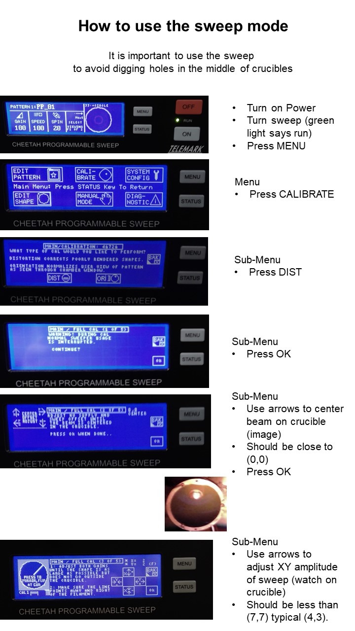
- Turn on the Telemark controllers for beam power and beam sweep (important, see info at bottom of page)
- Make sure the main shutter is Closed (to protect your sample)
- Turn on the high voltage (HV) – It should read about 7 kV (PLEASE DO NOT ADJUST; Contact the ANF manager if it is far from 7).
- Make sure the Filament current knob is set to 0 (zero) – then turn on Gun Control.
- Wait about 30s for the filament to pre-heat
- Select the desired beam sweep pattern – see below How to use the sweep mode, current best sweep amplitude is (4,2) for most sources
- Slowly begin ramping the filament current until the pressure in the main chamber begin to rise (read from ion gauge monitor)
- Slowly rise the filament current until the crystal monitor displays the desired deposition rate. NB: the heating of the source can be observed through the bottom view port by looking at the mirror on the other side of the chamber.
- If the crystal monitor indicates no deposition while the source appears very hot probably indicates that the wrong crystal has been chosen. In such a case, slowly turn down the current, wait 5 minutes for the source to cool, and start again using the other crystal choice.
- If there is still a problem, contact the ANF personnel.
- When the desired deposition rate has been reached and stabilized, the deposition may proceed:
- ZERO the crystal monitor and, at the same time:
- OPEN the main shutter by opening the Shutter switch on the control box
- When the desired thickness has been deposited, close the main shutter by closing the Shutter switch on the control box
- Slowly ramp down the filament current.
- Turn the Gun Control off – you may leave the HV on if you will do a second deposition. Otherwise, turn HV off.
- Wait 10 minutes for the source to cool: do not change the source crucible until the current source has cooled sufficiently.
- If a second deposition needs to be made on the same film (eg gold following titanium), you may now select it using the source selection knob and repeat steps 3 to 8.
- Once the source has cooled, you may unload the sample which is done by reversing the loading procedure.
Table of density and z-ratio for common materials