Introduction:
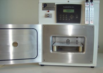
Figure 1: Front view of PE-50 plasma etcher with door open. The gases are controlled by the manual mass flow controllers (visible at upper right) while the plasma power is controlled by the rotary knob to the left of the touchpad panel.
The system uses Ar and O2 gases and is currently mostly dedicated to O2 plasmas. It can be used for descum, or total removal of photoresist. Figure 1 shows a front view of the system with the chamber door opened to display the tray where samples are mounted.
Author:
Mario Beaudoin,
- Rev. 01, November 2016.
- Rev. 02, January 2024.
Process expectation:
AZ4110P photoresist etch rate is roughly 20 nm/min with an O2 plasma at full power and 200 mTorr pressure.
Pre-process check:
Choosing menus and setting plasma parameters
Setup menu
- Plasma time: 30s to several minutes
- Vacuum Set Point: recommend 110 mTorr; NB: this is NOT the process pressure but the lowest vacuum attained during pumpdown prior to injection of process gas
- Atmospheric Vent: 00:59 min
- Purge Vent: 45s
- Gas Stabilize: 59s (this is roughly the time needed to adjust the plasma pressure by controlling the gas flow)
- Vacuum Alarm: 3:00min (please notify the ANF management if this happens; probable causes are improperly closed door or failing vacuum pump)
- Auto-cycle: Make sure it is ON (Enter key toggles the condition)
- Hit the UP arrow to get back to the main menu
Commands menu generating plasma
The Commands menu toggles between Plasma, Cycle-ON and Cycle-OFF possibilities. Only the Plasma needs to be used if the setup chose Auto-cycle. To begin a process, chose the desired plasma power by turning the black knob at the left of the touchpad clockwise: the Maximum power is 100W. From the Commands-Plasma menu, hit the Enter key. The display will show the Vacuum Setpoint (S) and the Attained Vacuum (A). When the A value reaches the S value, the gases are turned on. At that point, depress the Left Arrow on the touchpad: the screen will display the chamber pressure. You now have the Gas Stabilize time, chosen at Setup stage, to purge the lines of residual gas and to set the desired plasma pressure. Follow this procedure:
- The MFC controller valve should have been left open from the previous usage
- Otherwise, open the mass flow controller (MFC) valve until the little black ball hits between 15 and 20 sccm
- Adjust the MFC flow to control the plasma pressure: pressure should be between 250-300 mTorr for best plasmas (for oxygen, 15 cc/min flow yields roughly 280 mTorr pressure). NB: the pressure should be below 300 mTorr.
- The plasma will turn on by itself and will be indicated by the red light just above the power knob.
- An oxygen plasma should be white and and Argon plasma is purplish blue
Removing and terminating the process
The plasma will stop on its own. If Cycle-ON was properly set at the Setup stage, the system will purge the chamber. When the cycle has completed, the display will be back to Commands Menu (see Figure 2). Leave the MFC valve open at its current setpoint, remove your samples and close the door.
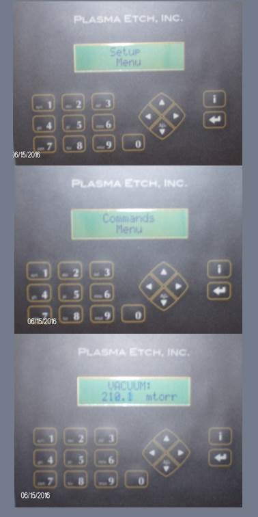
Figure 2: Control panel touchpad. The process parameters are set in the Setup menu while the process is controlled in the Commands menu.